

Views: 0 Author: Site Editor Publish Time: 2026-07-10 Origin: Site


Misinterpreting battery datasheets leads to costly prototyping errors, compliance failures, and product safety risks. You might think grabbing the highest capacity cell solves all operational demands. However, while manufacturer spec sheets appear dense, evaluating them systematically separates reliable power sources from exaggerated marketing claims. Relying on unverified raw numbers easily ruins hardware longevity. This guide translates complex technical parameters into a clear, decision-stage framework for evaluating and shortlisting the right components. The journey begins directly at the individual cell level. We will examine how discharge multipliers interact against thermal limits. You will discover exactly how to navigate complex supplier documents. Mastering these fundamentals ensures your devices function securely under harsh conditions. Stop guessing your hardware specifications. Rely on hard data. You can protect your engineering efforts by reading parameters accurately. Every successful product launch relies on secure energy storage. This fundamental knowledge prevents field failures.
Selecting batteries based solely on price or maximum stated capacity often results in underpowered devices or premature battery degradation. You cannot build a reliable product on false assumptions. Many designers scan a datasheet quickly. They spot a massive capacity number. They immediately assume it represents the best value. This oversight creates severe downstream consequences. The hardware might run perfectly in a climate-controlled laboratory. However, real-world deployment stresses the components differently. Batteries degrade rapidly when pushed past their intended operational limits.
You face significant engineering bottlenecks when specifications do not align with real-world current draws. Two major hardware integration risks always emerge. The first is thermal throttling. Batteries generate heat during discharge. An undersized cell cannot dissipate this heat effectively. The internal temperature spikes dangerously. Sensors detect this heat anomaly. They force the device to reduce power output. The second major risk involves voltage sag. High current demands pull energy faster than the internal chemistry can supply it. The voltage plummets rapidly. Your hardware interprets this drop as an empty fuel tank. It powers down abruptly.
A successful evaluation aligns the battery’s continuous performance thresholds with the device's peak operational demands. You must map out your exact energy consumption profile. Measure the steady-state current required to keep the system running. Determine the momentary spikes needed to activate motors or transmit data. Comparing these specific numbers against manufacturer documentation ensures compliance and user safety. You eliminate guesswork. You stop relying on inflated marketing brochures. The focus shifts entirely to verifiable engineering metrics.
Voltage acts as the electrical pressure pushing energy through your circuits. You must understand the difference between nominal voltage and peak voltage. Nominal voltage represents the average operating pressure during a standard discharge cycle. Engineers use this figure for general capacity calculations. Peak voltage occurs immediately after a full charge. A standard cell might show 4.2 volts at absolute peak. It drops to its 3.7-volt nominal state shortly after use begins. You design your hardware to accommodate this natural downward curve.
Evaluating cut-off limits requires extreme precision. The cut-off voltage is the absolute minimum operating threshold. Designing around the cut-off voltage prevents deep discharge damage and triggers the Battery Management System (BMS) correctly. Draining a cell below this limit alters its internal chemistry. Copper dissolves inside the casing. Recharging it later forms microscopic metal spikes. These spikes puncture internal separators. Fire hazards increase dramatically. Strict cut-off protocols prevent this catastrophic degradation.
You can define capacity as the total fuel tank of your power source. We express this metric in milliampere-hours (mAh) or ampere-hours (Ah). It measures how many amps the cell provides over one hour. However, you must emphasize Watt-hours (Wh) as the truer metric for cross-comparing different voltage systems. Capacity alone deceives designers. Energy (Wh) combines both capacity and voltage. It calculates the actual physical work the cell performs. A 10Ah cell at 3.2V holds 32Wh. A 10Ah cell at 12V holds 120Wh. Always evaluate the Watt-hour rating.
You must apply a skeptical check against marketing materials. Warn against physically impossible capacity claims. Unscrupulous vendors manipulate labels to drive sales. For example, standard 18650 cells claiming over 4000mAh are chemically impossible. Standard commercial limits cap around 3500mAh to 3600mAh. Any higher number indicates a fake product. Validate these claims through physical dimension checks and weight measurements. Reliable manufacturers provide verifiable data curves. They never print physically impossible metrics.
The C-rate determines maximum safe current draw. It acts as a multiplier against the stated capacity. A 1C discharge rate drains the entire unit in exactly one hour. A 2C rate drains it in 30 minutes. A 0.5C rate takes two hours. Understanding this math prevents hardware damage. A 3000mAh cell rated for 10C can output 30 amps continuously. Exceeding the stated C-rate generates excess heat. It destroys the internal structure rapidly.
Implementation reality forces designers to accept a fundamental compromise. Highlight the trade-off: high-capacity cells often have lower discharge rates, while high-drain cells sacrifice total capacity. You cannot have maximum energy storage and maximum discharge speed simultaneously. Thick electrodes store more energy but release it slowly. Thin electrodes release energy quickly but store less overall volume. You must choose one priority. Match this priority to your specific device requirements.
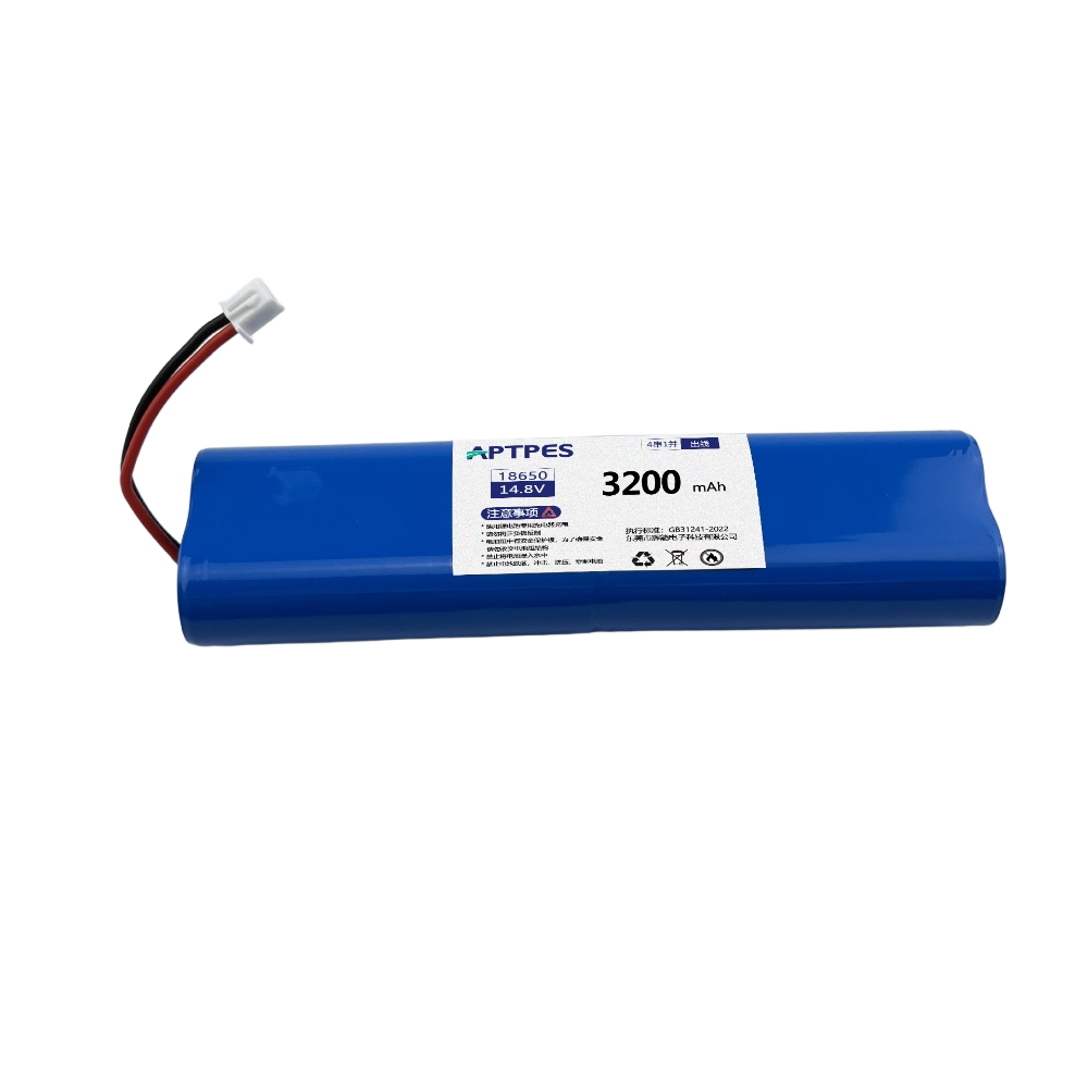
Physical size dictates how you integrate power into your product housing. Discuss how a cylindrical Single Lithium Battery scales into a larger pack. Engineers combine individual cylinders in series to increase voltage. They connect them in parallel to boost capacity. A standard 21700 cell serves as a versatile building block. You can assemble thousands of them to power an electric vehicle. You can use just four to run a laptop. This scalability simplifies manufacturing logistics.
Match form factors to use-cases precisely. Cylindrical formats provide superior mechanical durability. Their rigid steel cases resist impact forces. The round shape naturally creates thermal spacing. Air flows easily between clustered cylinders. Pouch cells lack rigid enclosures. They swell slightly during charging. However, they excel in ultra-thin consumer electronics. Smartphones require pouch designs to maintain slim profiles. Prismatic cells use large aluminum blocks. They deliver massive capacities. Industrial energy storage systems rely heavily on prismatic designs.
You must evaluate internal chemistry alongside physical shape. Lithium Iron Phosphate (LFP) dominates heavy-duty applications. Highlight its superior cycle life. Most LFP units endure 2000+ cycles before degrading significantly. Highlight its thermal stability. LFP carries a much lower risk of thermal runaway. It tolerates physical punctures and overcharging better than alternatives. This chemistry works best for stationary storage or longevity-focused applications. Solar backup arrays utilize LFP exclusively. The safety margins justify the slightly heavier weight.
Nickel Manganese Cobalt (NMC) targets entirely different engineering goals. Highlight its higher energy density. NMC packs significantly more energy into a smaller footprint. We select NMC for weight-sensitive applications. Drones require lightweight power to maximize flight times. Portable power tools need high energy in compact handles. Electric bicycles use NMC to extend riding range. This chemistry suffers a shorter cycle lifespan compared to LFP. However, the immediate performance benefits outweigh the longevity concerns in mobile devices.
| Feature | LFP (Lithium Iron Phosphate) | NMC (Nickel Manganese Cobalt) |
|---|---|---|
| Cycle Life | 2000 to 5000+ cycles | 500 to 1500 cycles |
| Energy Density | Lower (Heavier physical weight) | Higher (Lighter physical weight) |
| Thermal Safety | Excellent (High runaway threshold) | Moderate (Requires strict monitoring) |
| Ideal Applications | Solar storage, industrial, marine | Drones, EVs, portable electronics |
Temperature dictates chemical behavior. Operating temperature ranges require strict observation. Note the critical difference between safe discharge temperatures and much stricter charge temperature limits. You can safely discharge many cells in freezing weather. The internal resistance generates enough heat to keep the reaction moving. However, avoiding charging lithium below freezing is absolute. Forcing current into a freezing cell causes lithium plating. Metallic lithium coats the internal anode. This creates permanent damage. It frequently leads to uncontrollable internal short circuits.
Internal Resistance (IR) provides a direct window into structural health. Frame IR as an indicator of manufacturing quality and cell health. A brand-new unit should measure very low internal resistance. Lower IR means less heat generation during high-power tasks. Electricity flows freely. High IR acts like a clogged water pipe. The energy struggles to move. It converts into dangerous waste heat. Tracking IR over time helps predict end-of-life failures. Sudden spikes in IR indicate internal degradation.
Commercial deployment requires strict legal adherence. List non-negotiable compliance markers for commercial rollouts. You must verify UN38.3 certification first. This proves transportation safety. Shipping companies refuse uncertified cargo. Next, look for UL 1642. This governs individual cell safety against physical abuse. It tests crushing, burning, and overcharging scenarios. Finally, verify IEC 62133 compliance. This standard ensures international safety consistency for portable applications. You cannot launch a global product without these documents. Request the actual certificates from your supplier immediately.
Properly interpreting battery specifications bridges the gap between theoretical hardware design and real-world reliability. You now possess the framework to evaluate voltage metrics, capacity claims, and discharge multipliers accurately. You recognize how physical form factors dictate spatial planning. You understand how chemical properties influence thermal safety. Navigating the dense numbers inside supplier documents separates successful engineering from costly prototyping failures. You can confidently identify authentic technical data and ignore inflated marketing promises.
We encourage you to audit your current power requirements before reaching out to suppliers for validated datasheets and samples. Document your precise operating voltage. Calculate your sustained and peak current draws accurately. Define your maximum physical space constraints. Map out your environmental temperature expectations. Armed with these specific variables, you can approach manufacturers with authority. Demand detailed discharge curves. Procure physical test batches. Start building your hardware on a foundation of verified, reliable energy storage today.
A: Cross-reference the physical size and chemistry. For example, commercial 18650 lithium-ion cells max out around 3500mAh-3600mAh. Anything claiming 5000mAh+ in that form factor is chemically improbable and indicates an untrustworthy supplier.
A: Cycle life assumes ideal laboratory conditions (e.g., 0.2C discharge rate at 25°C). Operating at higher temperatures, fast-charging constantly, or discharging to 0% significantly reduces practical lifespan.
A: Yes. Even a single cell requires a basic protection circuit module (PCM) or BMS to prevent over-voltage during charging, under-voltage during use, and over-current faults, ensuring safety and compliance.
A: Continuous discharge is the current the battery can output indefinitely without overheating. Peak discharge is a temporary burst (usually lasting only a few seconds) for starting motors or handling surges. Always design your baseline load around the continuous rating.


